PanelMaster is an open-source, portable, lightweight yet feature-complete
CAD application for electrical control panel layout design, focused on
rapid iteration and high-quality visual outputs.
This is the initial screen you see upon launching PanelMaster:
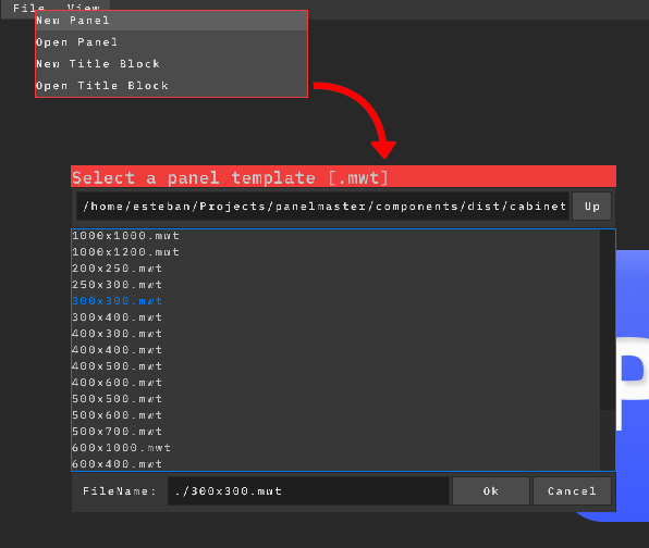
To create your first panel, select File > New Panel
and choose the template for your enclosure using the file dialog:
Enclosure templates use the .mwt format. They specify the cabinet's
physical dimensions and its internal mounting surfaces (such as backpanels or
doors) where components can be placed. Built-in templates are located in
components/cabinets.
If the file is valid, the Workspace will open with the cabinet in it.
The Workspace can be opened or closed at any moment from the
View menu, like any other window, or by pressing
Esc while hovering over it.
If the file is invalid or corrupted, an error message will log in the
bottom-left corner.
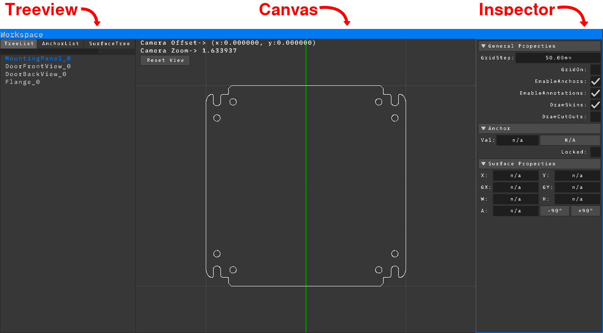
The Workspace is divided into three main areas: the Treeview, the Canvas,
and the Inspector.
Treeview: Displays the entities that make up the enclosure
currently being edited. It contains four interchangeable tabs:
TreeList: Shows the base surfaces available for
placing components, according to the selected template.
AnchorList: Shows the anchors and their constraints
present on the active base surface (anchors are explained later).
SurfaceTree: Displays the hierarchy of surfaces or
components placed on the selected base surface.
Annotations: Displays the annotations and dimensions
present on the active base surface.
Canvas: The main workspace area, where you can select and
move surfaces and anchors. Use the mouse wheel to zoom, press and hold
the mouse wheel to pan, and click the Reset View button
in the top-left corner at any time to reset the camera to (0,0).
Inspector: Displays and allows you to modify the properties
of selected surfaces or anchors, as well as general workspace properties.
Surfaces Basics
Surfaces are the core components that make up an enclosure in PanelMaster
and are stored as .mwc files.
They are structured hierarchically: when you move or rotate a parent surface,
all of its child surfaces automatically follow, making it easy to reposition
entire blocks of components at once.
To add a surface, right-click on the intended parent surface and select
Add Child Surface, then choose the .mwc
file from the file dialog.
Built-in surface files are located in components/.
To move a surface in the Canvas, click and drag it. From the Inspector,
you can view both its global position and its relative position to its
parent, as well as adjust its rotation.
To Remove a surface and its children, right click on it and select
Delete Surface.
To duplicate a surface, right-click on it and select
Duplicate Surface, then enter the desired number of copies.
Each new copy will be set as a child of the previous one, creating a nested hierarchy.
To align a surface and its children, right-click on it and select
Align Children, then choose one of the following alignment options:
Align Ahead: Aligns only the immediate child surfaces forward.
Align Ahead (Recursive): Aligns all child surfaces forward,
including deeper nested descendants.
Align Behind: Aligns only the immediate child surfaces backward.
Align Behind (Recursive): Aligns all child surfaces backward,
including deeper nested descendants.
Then enter the offset distance to specify the spacing between each aligned element.
To flatten a surface hierarchy, right-click on the parent surface,
select Flat Surface, and choose one of the following operations:
Flat from Father: Moves immediate child surfaces up to
the same hierarchical level as the parent. The child surfaces keep
their own descendants intact.
Flat from Father (Recursive): Moves the surface and all
of its descendants up to the same hierarchical level as the parent.
Flat Children: Promotes all nested descendants to become
direct children of the selected parent surface, creating a single-level
child hierarchy.
To change the display order of surfaces, right-click on the target surface
and select Shift Surface Up or
Shift Surface Down.
To reparent a surface, select the child surface with left-click, then hold
Left Shift and left-click the target parent surface.
Right-click either of the selected surfaces and select
Reparent Surface. Then, choose one of the following
positioning options:
Keep Current Position: Keeps the reparented surface
at its current spatial coordinates.
Center in New Parent: Moves the reparented surface
directly to the local origin (0,0) of its new parent surface.
Anchors
Anchors are the parametric foundation of PanelMaster. They provide real-world
dimensions (mm), serve as reference points for on-screen annotations, and
control the behavior of extensible surfaces. Anchors can be either horizontal
or vertical, and they can have various types of constraints established between
each other and with surfaces.
To add an anchor, right-click on one of the four main anchors of a base
surface and select Add Offset. This creates a new anchor
bound by an offset constraint to the original anchor. Use the
Val parameter in the Inspector to define the exact distance
in mm between the new anchor and the original.
To move an anchor in the Canvas, click and drag it to the desired position.
However, if an anchor is restricted by a constraint or has been locked by
the system or the user, it cannot be moved manually.
To add multiple anchors at once, hold Left Shift and left-click
to select more than one main anchor, right-click, and select
Add Offset. Choose Multiple from the menu
to create a new offset anchor for each selected reference anchor simultaneously.
To delete an anchor, right-click on it and select
Delete Anchor.
To add a center anchor between two parallel anchors, select the first anchor
with a left-click, then hold Left Shift and left-click the
second parallel anchor. Right-click either of the selected anchors and select
Add Center. This creates a new anchor constrained directly
to the midpoint between the two reference anchors.
To mirror an anchor across a reference anchor, select the target anchor with
a left-click, then hold Left Shift and left-click the second
anchor to serve as the axis. Right-click either anchor and select
Add Mirror. This creates a new anchor constrained symmetrically
opposite the first anchor relative to the selected reference.
To release an anchor from its constraint, right-click on the anchor and select
Free Constraint.
Extensible Surfaces
Extensible surfaces are specialized surfaces capable of dynamic resizing,
such as cable ducts or DIN rails. Unlike standard surfaces, they ignore
hierarchical position settings and respond exclusively to anchor constraints.
Despite this parametric positioning behavior, extensible surfaces maintain
standard parenting capabilities: they can be parented to other surfaces, and
child surfaces can be parented to them.
To add an extensible surface, select three reference anchors: two parallel
anchors and one perpendicular anchor. Left-click to select the first anchor,
then hold Left Shift and left-click the remaining two. Right-click the
intended parent surface, select Add Child Surface, and choose
an extensible surface file from the file dialog.
Extensible surfaces also use the .mwc file format.
Built-in extensible surface files are located in
components/extensibles.
To modify the length or position of an extensible surface, click and drag
its reference anchors in the Canvas, or adjust their offset values from
the Inspector.
Extensible surfaces can also act as parent surfaces: you can right-click
an extensible surface and select Add Child Surface to parent
other surfaces to it, just like with standard surfaces.
To control the positioning side of an extensible surface, select the surface
and modify the AxisAlign parameter in the Inspector.
This parameter specifies which side of the main perpendicular anchor the
surface is rendered on.
Extensible surfaces can be added with a single reference anchor selected,
in which case the two closest perpendicular anchors on either side of the
mouse will be selected automatically. Explicit selection is recommended
when working with many anchors.
To modify the cuts at each end of an extensible surface, select the surface
and adjust the LCut and RCut properties
under Anchor Setup in the Inspector. The value specifies the distance in
millimeters from the corresponding edge at which the cut is made. Positive
and negative values produce cuts in opposite directions.
For example, if the extensible surface is 25 mm wide, setting the cut
value to 25 mm produces a 45-degree cut.
When adding an extensible surface with four reference anchors selected,
two horizontal and two vertical, a frame is automatically created using
the selected extensible surface, with the corner cuts applied automatically.
Annotations
Annotations are the element used in PanelMaster to visualize dimensions
between two anchors.
They are purely visual and do not modify the actual dimensions.
To set an exact dimension, modify the corresponding anchor value instead.
To add an annotation, select two anchors: left-click the first anchor,
then hold Left Shift and left-click the second. Right-click either selected
anchor and select Add Annotation. The annotation will appear
between the two anchors at the mouse position.
To move an annotation, simply drag it with the mouse.
To delete an annotation, right-click on it and select
Delete Annotation.
To add extension lines to an annotation, hold Left Shift and click the
annotation, then drag the mouse to the desired position.
To remove the extension lines from an annotation, right-click the annotation
and select Disable Extension Lines.
To switch the side on which the annotation text is displayed, right-click
the annotation and select Flip Side.
To hide an annotation, right-click it and select
Hide/Show Annotation. To show it again, right-click the
annotation from the Annotations section in the TreeView and select
Hide/Show Annotation again.
More Surface/Anchor Features
Several features are available to allow surfaces and anchors to interact in
more complex ways, primarily intended for handling door layouts and similar
configurations.
When adding an anchor, its position can be locked to prevent accidental
changes by selecting the anchor and enabling the Locked
checkbox under the Anchors section in the Inspector.
The movement of a surface can be restricted along either axis by enabling
Fixed Local X or Fixed Local Y under the
Surface Properties section in the Inspector. When adding a child surface
to an extensible surface, its local Y axis is locked by default to simulate
the behavior of a component sliding along a rail.
Similarly to annotations, anchors and surfaces (including their descendants)
can be hidden and shown from both the Canvas and the TreeView.
To set an existing anchor as the offset of another anchor, left-click the
anchor to be used as the offset, then hold Left Shift and
left-click the anchor that will use the offset. Right-click either anchor
and select Set as Offset.
To set an existing anchor as the center between two other anchors, left-click
the anchor to be used as the center, then hold Left Shift
and left-click the two outer anchors. Right-click any of the three anchors
and select Set as Center.
To set an existing anchor as the mirror of another anchor, left-click the
anchor to be used as the mirror, then hold Left Shift and
left-click the anchor to be mirrored, followed by the anchor to be used as
the axis. Right-click any of the three anchors and select
Set as Mirror.
To create precise layouts, a surface can be fixed to one or two anchors.
Select the surface and the anchor, right-click the surface, and select
Fix to Anchor. This can be repeated with an anchor on the
opposite axis to position the surface at the intersection of the two anchors.
To free a surface from one or more anchors, right-click the surface and
select Free From Anchor. If the surface is fixed to multiple
anchors, select whether to remove the Vertical or Horizontal constraint.
Anchors can also be aligned to surfaces. Select the surface and the anchor,
right-click the anchor, and select Fix to Surface. Once fixed,
the anchor value can be adjusted to set an offset relative to the surface
position, or the anchor can be locked to prevent accidental movement.
To release an anchor from its surface constraint, right-click the anchor and
select Free Constraint.
When combined with the different anchor constraints, these features allow
for surprisingly complex, responsive, symmetric, and fully parametric
component layouts.
Components intended for door mounting include their cutout dimensions.
To display them, enable or disable DrawCutOuts under General Properties
in the Inspector. The DrawSkins option in the same section can be disabled
to hide the component when it gets in the way.
Right-clicking a component provides the Create Boundary Anchors
and Create CutOut Anchors options, which automatically
create anchors at the component's maximum and cutout dimensions. These anchors
can then be used for layout positioning or annotations.
Boundary Anchors are especially useful for extensible components,
for example, to position rails between cable ducts.
To activate a surface as a Ghost Reference, hold
Left Shift and left-click a different base surface in the
TreeList tab of the TreeView.
The surface will be displayed as a semi-transparent reference under the
currently selected surface. Holding Left Shift and left-clicking the active
ghost again will deactivate it.
Right-clicking the ghost surface in the TreeList tab of the
TreeView provides options to flip the ghost along the X or
Y axis. This can be used to accurately represent the back side of a door
when viewed from the front, as if through an X-ray.
Projections are used to transfer measurements from one base surface to
another. They allow an anchor on one surface to continuously match the
value of an anchor on a different surface. To set a projection constraint,
first set a Ghost Reference for the surface from which the
projection will be taken, then select the anchor to be used as the projection
on that surface. Return to the target surface and select the anchor that will
receive the projection. Finally, right-click and select
Set as Projection or
Set as Inverted Projection (if the ghost is flipped).
To release an anchor from its projection constraint, right-click the anchor
and select Free Constraint.
Bonus
The entire panel can be replaced at once while automatically adjusting
most dimensions. Go to File > Change Panel and select
any panel.
If the replacement panel has fewer base surfaces than the original, those
surfaces and their contents will be deleted and any anchor constraints
referencing an anchor on a deleted surface will also be released.
Documents
Documents are the structures used by PanelMaster to generate technical
documentation. Each project contains a single document, which is edited
through the Document Editor, accessible from View > Document Editor.
The document is stored as part of the project and requires no separate file.
Once completed, it can be exported as a PDF for viewing, printing, or sharing.
Documents are made up of pages. All pages in a document share the same page
size, which is defined in millimeters and defaults to A4 landscape
(420W × 297H). Each page can independently enable or disable its frame and
adjust its frame margins, which are also defined in millimeters.
Each page also has its own list of entities. Entities are the elements that
can be added to a page, each with its own position on the page. Additionally,
each entity type has its own set of editable properties, which can be configured
directly from the Document Editor. Currently, PanelMaster supports the
following entity types:
Surfaces: Panel surfaces that can be displayed as part of the document.
Text: Text elements that can be placed on the page.
Stickers: Image elements that can be placed on the page. Transparency is not currently supported.
Title Blocks: Explained later.
Document Editor
The Document Editor can be opened at any time from View > Document Editor.
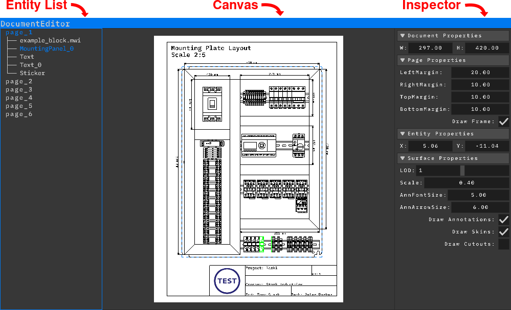
It is divided into three main areas: the Entity List, the Canvas, and the Inspector.
Entity List: Displays the pages contained in the document,
as well as the entities belonging to each page.
Canvas: Displays the currently selected page, where its
entities can be selected and moved.
Inspector: Displays and allows you to modify the properties
of the entity selected on the current page.
Usage:
When creating a new project, the document contains no pages by default.
To create a page, right-click in the Entity List and select New Page.
To modify the page size, use the W and H parameters under the
Document Properties section of the Inspector.
To add a frame to the page, enable Draw Frame under the Page Properties
section of the Inspector. Once enabled, the LeftMargin, RightMargin,
TopMargin, and BottomMargin parameters become available in the same
section and can be used to adjust the margins on each side of the frame.
To add a surface to a page, right-click in the Entity List and select
Add Surface.
To move a Surface entity, click and drag it in the Canvas.
To modify a Surface entity, select it from the Entity List or Canvas.
The following options are available under the
Surface Properties section of the Inspector:
Scale: Changes the size of the surface on the page.
LOD: Controls the level of detail used to draw the
components on the surface. Most components have three different
levels of detail available.
For large surfaces displayed on small pages, using a lower level
of detail can make the drawing cleaner and easier to read.
AnnFontSize: Changes the font size of annotations
displayed on the surface.
AnnArrowSize: Changes the size of annotation arrows.
Draw Annotations: Enables or disables annotations
on the surface.
Draw Skins: Enables or disables the drawing of
component skins on the surface. Extensible surfaces are still drawn
when this option is disabled.
Draw Cutouts: Enables or disables the cutout areas
of components. When enabled, components with cutout geometry display
their cutouts using a diagonal line pattern.
To add a text entity to a page, right-click in the Entity List and select
Add Text.
To move a Text entity, click and drag it in the Canvas.
To modify a Text entity, select it from the Entity List or Canvas.
The following options are available under the
Text Properties section of the Inspector:
Text: Specifies the text to display.
Multiline text is supported.
Size: Changes the size of the text.
Left, Center, Right: Aligns multiline text relative
to the longest line.
PanelMaster currently does not support fixed-size text boxes.
As a workaround, you can add a line containing only spaces to
set the desired width. Other lines will then be aligned relative
to this line.
R, G, B: Controls the color of the text using
separate red, green, and blue values.
To add a sticker to a page, right-click in the Entity List and select
Add Sticker, then choose a valid image file from the
file dialog.
To move a Sticker entity, click and drag it in the Canvas.
To modify a Sticker entity, select it from the Entity List or Canvas.
The Scale option under the
Sticker Properties section of the Inspector changes the
size of the sticker on the page.
To delete an entity, right-click it in the Entity List or Canvas and select
Delete Entity.
To delete a page, right-click in the Entity List and select
Delete Page. This deletes the active page.
To duplicate a page, right-click in the Entity List and select
Duplicate Page. This creates a copy of the active page,
including all of its entities.
To change the drawing order of an entity, right-click it in the Entity List
and select Shift Up or Shift Down.
Exports (DXF, SVG)
To export the cutouts of a surface tree as a .dxf file,
right-click the desired surface in the TreeList tab and select
Export Cutouts. A file dialog will then open to choose the output location.
The exported file contains two layers: SURFACE, containing the surface outline,
and CUTOUTS, containing the cutout geometry.
The DXF format and its separate layers are intended for manufacturing workflows,
such as machining or laser cutting the cabinet door.
To export a base surface as an .svg file, add it as a Surface entity to any page
in the project's Document, then right-click the entity and select Export to SVG.
The exported SVG preserves the entity's display parameters, such as LOD,
annotation settings, Draw Skins, and Draw Cutouts,
producing a result visually identical to the Surface entity in the Document.
SVG export is useful for importing drawings into other applications with more advanced document editing
capabilities than PanelMaster currently provides, such as Microsoft Word or Inkscape. SVG performance is
not highly optimized at the moment, so exported files may be relatively heavy.
Title Blocks
Title Blocks are the information panels commonly found on technical drawings.
In PanelMaster, they are fully customizable and are not limited to a fixed layout.
They can be created with different divisions, positions, and text sizes to suit
the needs of each document.
Title Blocks are divided into Rects, which can contain text and an optional label.
Title Blocks can be saved and loaded for use in other projects. They use the
.mwi file extension, making it possible to reuse common layouts
across different projects. Once created, Title Blocks are used as entities on
document pages.
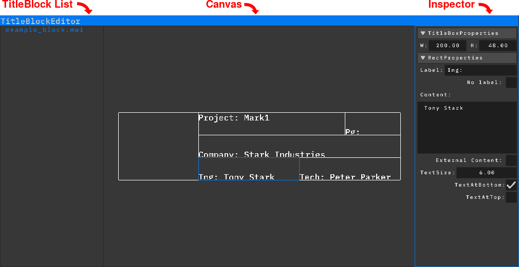
Title Block Editor
The TitleBlock Editor can be opened at any time from View > TitleBlock Editor.
It is divided into three main areas: the TitleBlock List, the Canvas, and the Inspector.
To create a new Title Block, right-click in the TitleBlock List and select
New Title Block, or use File > New Title Block.
To save a Title Block, right-click it in the TitleBlock List and select
Save Title Block As, or use File > Save Title Block As.
To open an existing Title Block, right-click in the TitleBlock List and select
Open Title Block, or use File > Open Title Block.
Once a Title Block has been created, its dimensions can be changed using
the W and H options under the
TitleBlock Properties section of the Inspector.
To select a Rect, left-click on it. Its Rect Properties
will then be displayed in the Inspector.
To divide a Rect, right-click on it and select
Split Horizontally or Split Vertically,
depending on the desired direction. Then, enter the number of divisions
in the Divisions input to specify how many sections the
Rect should be divided into.
To resize a Rect, click and drag any of its edges.
To delete a Rect, resize it until one of its dimensions reaches zero by
dragging one of its edges onto the opposite edge.
When a Rect is selected, its available parameters are displayed under the
Rect Properties section of the Inspector:
Label: Specifies the identifier of the Rect.
Each Rect must have a unique label.
No Label: Hides the Rect's label. This can be useful when
placing a sticker inside the Rect, when the label does not align correctly,
or when no label is needed.
Content: Specifies the content displayed inside the Rect.
By default, the same content is used for every instance of the Title Block.
External Content: Makes the Rect's content independent
for each instance of the Title Block inside a document. When enabled,
its content can be set separately from the Document Editor.
TextSize: Sets the size of both the Rect's content and its label.
TextAtBottom: Aligns the text against the bottom edge of the Rect.
TextAtTop: Aligns the text against the top edge of the Rect.